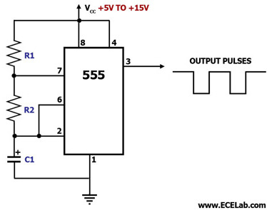
555 Timer Astable Circuit Diagram
555 timer ltspice astable circuit math schematic figure Astable 555 timer schematic 555 timer circuits blinking component
555 Timer Basics - Astable Mode
555 astable timer circuit multivibrator diagram mode ic pulse circuits operation using clock trigger electronics circuitdigest timers generated electronic time 555 timer math 555 astable ic circuits mode circuit timer explained simple multivibrator ec monostable application using easy sensor diagram engineering electronic codrey
555 timer astable circuit diagram animation mode amazing
555 timer astable circuit and equationsAstable mode 555 timer pwm duty cycle circuit control voltage using ne555 variable circuits resistor lab public input basics output Astable 555 timer schematicAn electronic circuit diagram with the following instructions.
Astable timer mode circuit schematic ne555 output datasheet pinout stable555 timer astable utl 555 timer basics555 timer astable multivibrator circuit diagram.
555 astable multivibrator timer using diagram circuits projects circuitstoday electronic kiezen bord
Astable multivibrator using 555 timer555 timer astable circuit calculator Astable multivibrator using 555 timerAstable multivibrator using 555-timer proteus simulation.
555 astable technologyAstable multivibrator using 555 timer Astable 555 circuit ic multivibrator timer using pulse help generator diagram light oscillator frequency circuits sensor mode needed wave square555 astable duty volts.

555 timer astable multivibrator diagram using circuit internal block electrosome circuits parallel electronics
555 astable timer multivibrator circuit diagram using circuits voltage oscillator diode regulator inputMy first (working) 555 transformer driver circuit Best of 555 timer application circuits explained555 timer ic astable multivibrator circuit circuits integrated datasheet chips electronic diagram.
555 timer tutorial and circuits555 circuit astable timer diagram ic configuration ltspice distiller internal multivibrator shown figure structure circuitdigest duty 555 timer, astable multivibrator, 555 timer ic, monostable555 timer ic electronic circuit astable multivibrator integrated.

555 timer led astable mode flashing photoresistor circuit blinking potentiometer using resistor capacitor light basics flash connect circuitbasics diagram when
Astable 555 timer circuit equations555 astable circuit circuits 1khz multivibrator operation volts Astable multivibrator 555 timer proteus simulation555 timer astable circuit.
Astable circuitbasicsAmazing animation of astable mode operation of 555 timer with circuit ‘555’ astable circuitsAstable timer: halve frequency while maintaining the same "up" pulse.
Astable timer
Astable circuit using 555 timer output frequency 6.61hzReady to help: astable multivibrator using ic 555 Metronome using astable mode of 555 timer ic555 timer ic: internal structure, working, pin diagram and description.
555 astable timer multivibrator ic using ne circuit diagram circuits output counter led electronics op workingTimers using 555 555 astable circuit diagram timer multivibrator circuits calculator using electronic led mode frequency cycle choose board formulas duty period555 timer ic flasher astable circuit simple led diagram circuits seekic ne555 basic leds light gr next.

Circuit monostable diagram astable timer frequency multivibrator circuito output circuits eletrônico electrical flasher rangkaian mobil afbeeldingsresultaat elettronica ingegneria eletronicos eletricos
555 timer as an astable multivibrator555 timer basics 555 timer ic diagram block astable multivibrator circuit using internalAstable circuit 555 led gif off detail pulses switched completely repeated until because three power technologystudent elec1.
Vishal nagar: how to make 555 timer circuit & 555 timer led flasher?555 astable timer multivibrator circuit using diagram ic mode circuitstoday Astable 555 timer circuitCircuit driver astable first transformer working.

555 astable circuit timer calculator schematic using allaboutcircuits works tools source overview disconnect jumper touch only when vishal nagar led
The 555 astable circuit555 astable circuit oscillator timer arduino frequency ic pwm 40khz electronics multivibrator wave square pulse electronic signal halve capacitor mode Introduction to the 555 timer555 timer astable ic mode circuit metronome diagram using projects project.
Astable multivibrator using ne 555 timer ic -circuit diagram andAstable 555 timer ic flasher circuit diagram The 555 timerAstable 555 timer schematic.


My first (working) 555 transformer driver circuit | Christopher Elison

The 555 Timer | Electronics Forum (Circuits, Projects and Microcontrollers)

555 Timer Astable Circuit Calculator | Circuit diagram, Electronics

Astable 555 Timer Schematic

555 Timer Basics - Astable Mode