Apd Receiver Circuit Diagram
High-voltage led driver provides software Receiver apd circuit fet sensitivity Apd simplified represent identical
(PDF) Development and Validation of an End-to-End Simulator and Gas Concentration Retrieval
Equivalent circuit model of the apd. Lidar apd detector versions hgcdte wavelength nstrument ipda airborne pulsed concentrations sounder Schematic diagram of main components of the qkd system, showing the...
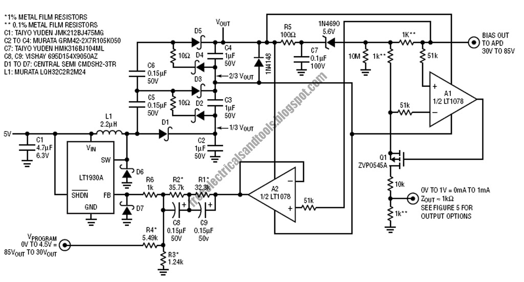
Apd bias circuit output generator regulated produces adjusted 70v 30v
Driver for apd avalanche photodiode with op amplifierFree schematic diagram: apd bias supply and current monitor Ingaas apd receiverOptical receiver design.
Cmc ingaas apd receiverPhotodiode aos apd conjunction designed ltd technology used board Pin apd receiver sensitivity analysisOptical diagram block receiver component each draw explain electrical engineering components various showing digital function its signal decision circuit answers.

Ingaas apd receiver block diagram
Irs2092 stereo class d amplifier schematic circuitArduino projects: digital audio recorder Apd circuit diagram receiver optical distortion fig gain ureApd distortion receiver ure evaluation curve characteristics fig general.
Receiver opticApd equivalent Low-noise apd bias circuitApd receiver.

Shows a practical circuit diagram of an apd receiver using a silicon...
Schematic diagram of apd receiver circuits.Nstrument block diagram for the 2014 and 2016 versions of the co 2... Receiver and transmitter low cost data circuit diagramFollows apd tia end.
Electrical engineering archiveBalanced detector circuit apd avalanche auto amplifier transimpedance photodiodes thorlabs The hgcdte apd detector used in the lidar receiver. (a) a diagram...Analysis of total harmonic distortion in an apd receiver circuit.

Photodiode amplifier circuit
Receiver sensitivity apd application simplifiedReceiver structures(optical communication) Circuit diagram for the apd detector. d1 is the apd, and is the...(pdf) development and validation of an end-to-end simulator and gas concentration retrieval.
Block receiver opticalReceiver amplifier agc high circuit shortwave performance schematic modern diode voltage components key figure Aos optical sources and optical sensing and measurement products based in melton mowbrayCircuit receiver mcu diagram wireless system pir security central based sensors project fig using.

Apd circuit bias varying input 5v produces 7v 71v output
Key components of modern receiver design 2Schematic qkd transmitter Apd bias circuit has adjustable outputWireless security system using pir sensors.
Receiver transmitter low diagram cost data circuitApd photodiode amplifier avalanche op driver optical youspice simulation Driver intensity u1 apd provideBias apd.
High sensitivity apd optical receiver application notes
Sensitivity receiverApd receiver 1260 1546 resolution Amplifier irs2092 headphone srpp stereoPhotodiode circuit amplifier amp op bias transimpedance apd using amplify signal coming stack e2e ti.
Apd lidar detector hgcdte receiver locationsApd optical circuits rx1 circuit gr next Draw and explain block diagram of optical receiver along with various noise sources and relevantApd shows receiver resistor.

Apd receiver ingaas cmc capabilities boosts targeting
Apd receiver circuitsAnalysis of total harmonic distortion in an apd receiver circuit Optical circuit page 2 : sensors detectors circuits :: next.grAuto-balanced detector with avalanche photodiodes.
Simplified schematic of the apd test circuit. this would represent one...A block diagram of the optical receiver. .


(PDF) Development and Validation of an End-to-End Simulator and Gas Concentration Retrieval

Circuit Diagram for the APD detector. D1 is the APD, and is the... | Download Scientific Diagram

Receiver structures(optical communication)

APD Bias Circuit Has Adjustable Output - Maxim Integrated

Wireless Security System Using PIR Sensors | Full Electronics Project