Ic 555 Circuit Diagram
Circuit diagram ic internal timer multivibrator daenotes stable figure Inverter circuit 555 ic ne555 power using circuits wave simplest diagram output single bridge homemade explored square type will projects 6 best ic 555 inverter circuits explored
integrated circuit - Cannot Understand the 555 IC Reset - Electrical
555 basic ic diagram 555 timer ic: introduction, basics & working with different operating modes 555 timer internal cmos invention circuitstoday
The history of 555 timer ic
Free circuit diagrams: ic555 tester circuit555 ic using bell simple circuits timer circuit diagram application door applications astable monostable explained touch two operated multivibrator 555 pwm circuit ic diagram simple using generating use generate mode circuits configuration following learn let homemade outputs monostable pinoutCircuit delay 555 timer ic off time.
555 timer ic astable multivibrator circuit circuits integrated datasheet chips electronic diagramMobile charger using ic 555 circuit diagram / mobile cellphone charger 555 basic ic diagram555 timer diagram block circuit chip does ne555 datasheet inside pinout work works eleccircuit look function will.

Ic 555 pinouts, astable, monostable, bistable modes explored
Astable multivibrator using ic 555 circuit |free electronic circuitHow does ne555 timer circuit work Introduction to the 555 timerDancing light using 555 timer.
555 timer astable multivibrator circuit diagram555 timer diagram internal ic circuit astable multivibrator monostable 555 astable circuit ic multivibrator using timer pulse generator help light diagram oscillator frequency circuits sensor mode audio needed waveIc 555 pin description and working [with formulas].

555 circuit ic diagram circuits simple using breadboard timer kanna oscillator
☑ integrated circuits 555 timerIc circuit diagram basic seekic Ic 555 delay timer circuitHow to use ic 555 for generating pwm outputs.
555 timer testing circuits555 timer circuit ic diagram astable mode tutorial random introducing randomnerdtutorials Ic 555 reset diagram circuit schematic cannot understand integrated electronics555 timer ic pin diagram features and applications.

Ic circuit diagram basic seekic
Timer 555 circuit schematic electronic ne555 circuits control lm555 applications multivibrator ic relay using off switch generator simple charger next555 timer monostable circuit diagram 555 ic circuits ic555 timer astable pinouts formulas homemade circuit internal bistable explored monostable555 circuit tester diagram ic simple timer circuits schematic chip test ic555 diagrams electronic pwm.
555 ic timer circuit diagram astable pinout pins multivibrator block description ic555 internal monostable using ground circuits board explain power555 ic diagram timer block internal ic555 circuits ne555 monostable explored modes astable pinouts bistable 555 timer diagram ic block circuit ne555 controller pins contradicting tutorials speed based resistive configuration electronicsIntroducing 555 timer ic.

555 timer circuit using light dancing diagram circuits pcb easyeda based ne555 astable gr next mode lm555 software cloud time
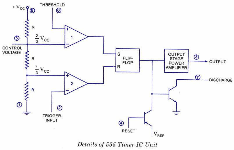
555 timer ic diagram block functional working internal principle schematic comparator avr pic ready help control digramReady to help: functional block diagram of ic 555 555 timer ic electronic circuit astable multivibrator integrated555 circuit timer modes basics operating fig.
Ic timer 555 block ic555 beginnersHow timer ic 555 works? Timer ic 555 testerIc converter ic555.
555 timer diagram ne555 chip ic electronics block electrical transistor circuit bistable discharge tutorial output multivibrator monostable engineering does logic
Integrated circuitIc 555 design note power inverters, electrolytic capacitor, conduction Kanna: simple circuits using ic 555555 timer tester ne555 engineeering.
Basic theory ic 555555 monostable circuit timer diagram schematic multivibrator circuits based electronic calculator circuitdiagram Timer 555 schematic555 ic monostable electroschematics timer capacitor 文章出處 resistor.

Simple touch sensitive switch circuit using 555 timer & bc547 transistor
Circuit touch 555 timer using sensitive switch diagram ic bc547 transistor simple ledBest of 555 timer application circuits explained 555 timer ic as a-stable multivibrator555 timer circuit diagram lm555 ic internal block schematic basic electronics theory electronic circuits simple data dual part chip led.
555 timer ic-block diagram-working-pin out configuration-data sheet .


555 Timer Monostable Circuit Diagram

How timer IC 555 works?

voltage - What would be the output of a 555 multivibrator ic in

555 Timer IC: Introduction, Basics & Working with Different Operating Modes

Introduction to the 555 Timer - Circuit Basics