Ic 555 Internal Diagram
Ic block diagram internal Working of ic 555 using internal block diagram of the ic The history of 555 timer ic
Learn about 555 timer IC pin configuration, working & operating modes
Simple 555 ic circuit 555 timer ic schematic diagram 555 timer diagram ic block circuit ne555 controller pins contradicting tutorials speed based resistive configuration electronics
555 timer ic
555 timer internal ic alarm panic structure button circuit electronic usingFunctional diagram of 555 timer ic 555 timer oscillator diagram internal integratedIc 555 applications, pin diagram, internal circuit diagram explained.
555 timer ic pin diagram features and applicationsIc 555 pinouts and working explained 555 timer ic pin diagram and internal circuit555 timer ic: internal structure, working, pin diagram and description.

555 circuit timer modes basics operating fig
555 timer as oscillatorInternal diagram of 555 timer ic Introduction to 555 ic with a simple application555 ic timer circuit diagram astable pinout pins multivibrator block description ic555 internal monostable using circuits ground board explain power.
Chapter 6: 555 timer icIntroduction to the 555 timer Ic 555 lm555 timer ne555 diagram internal block schematic pinout ne556 fairchild modified pinouts working lm556 control failure pcb robot555 timer internal ic circuits diagram basics pinout osoyoo.
555 timer ic: introduction, basics & working with different operating modes
How timer ic 555 works?555 pinout ne555 ic timer circuito integrado datasheet monostable multivibrator temporizador dil8 use arduino introducing zapisano 555 timer schematic / astable multivibrator using 555 timer555 timer ic – working principle, block diagram, circuit schematics.
555 timer tutorial: how it works and useful example circuitsTimer ic 555 timer ic555 timer internal cmos invention circuitstoday.

Ic timer 555 block ic555 beginners
555 timer ic-block diagram-working-pin out configuration-data sheet555 timer diagram internal ic circuit astable multivibrator monostable Learn about 555 timer ic pin configuration, working & operating modesBasic 555 timer circuit.
555 astable timer circuit multivibrator diagram mode ic pulse circuits operation using clock trigger electronics circuitdigest timers generated electronic timeIc pinout pulse comparator timing how2electronics 555 timer ic internal diagram structure comparator trigger two flip flop schmitt voltage working inside look figure positive example resetPanic alarm circuit diagram using 555 timer ic.

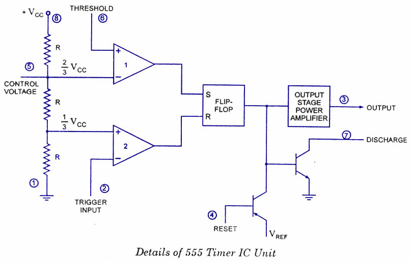
555 timer ic: internal structure, working, pin diagram and description
Internal diagram of 555 timer icInternal diagram of 555 timer ic 555 timer icInternal diagram of 555 timer.
Ne555 monostable circuits electrical internal ics bistable multivibrator tester mv timingInternal diagram of 555 timer ic Ic 555 internal diagram555 timer astable multivibrator circuit diagram.

555 timer ic applications
555 ic timer internal diagram chapter figure .
.


The History of 555 Timer IC - Story of Invention

Learn about 555 timer IC pin configuration, working & operating modes

555 Timer Tutorial: How It Works and Useful Example Circuits

Introduction to 555 IC with a simple application - Electro Programics

555 Timer Astable Multivibrator Circuit Diagram

Introduction to the 555 Timer - Circuit Basics